Nature Materials (2021)
Abstract
The magnetoelastic effect—the variation of the magnetic properties of a material under mechanical stress—is usually observed in rigid alloys, whose mechanical modulus is significantly different from that of human tissues, thus limiting their use in bioelectronics applications. Here, we observed a giant magnetoelastic effect in a soft system based on micromagnets dispersed in a silicone matrix, reaching a magnetomechanical coupling factor indicating up to four times more enhancement than in rigid counterparts. The results are interpreted using a wavy chain model, showing how mechanical stress changes the micromagnets’ spacing and dipole alignment, thus altering the magnetic field generated by the composite. Combined with liquid-metal coils patterned on polydimethylsiloxane working as a magnetic induction layer, the soft magnetoelastic composite is used for stretchable and water-resistant magnetoelastic generators adhering conformably to human skin. Such devices can be used as wearable or implantable power generators and biomedical sensors, opening alternative avenues for human-body-centred applications.
Main
Under an applied magnetic field, metal alloys such as TbxDy1–xFe2 (Terfenol-D) and GaxFe1–x (Galfenol) with a magnetoelastic effect (defined by the change of any magnetic property in certain materials under mechanical deformation; Supplementary Note 1) could alter their inner magnetization in response to external uniaxial stress1,2,3. Since the optimal mechanical-to-magnetic conversion efficiency is typically obtained under an applied stress of several megapascals4, the magnetoelastic effect is widely employed in civil engineering for building vibration control5. However, it has been ignored in the field of bioelectronics for the following reasons: the magnetization variation of a magnetic alloy in the biomechanical stress range is limited; the requirement of an external magnetic field induces structural complexity; and there exists a gigantic mismatch of the mechanical modulus (six orders of magnitude difference) between a magnetic alloy and human tissue6,7.
Bioelectronics are revolutionizing the future of human life by reshaping fields of medicine and healthcare into a more personalized form8. Biomechanical-to-electrical energy conversion is a promising pathway to realize self-powered bioelectronics in the imminent era of the Internet of Things9. This conversion is available 24 hours a day and provides up to 100 W output for an average person10. Current biomechanical energy conversion mechanisms, including piezoelectric and triboelectric effects, suffer limitations such as low current density and high internal impedance, which arise from their capacitive power generation via the electric dipole alignment11. Additionally, their output performance is vulnerable to the humidity caused by sweating, which limits their practical deployment in wearable and implantable bioelectronics12,13. Therefore, there exists a demand to search for an unexploited biomechanical-to-electrical energy conversion mechanism featuring high current output, low internal impedance and waterproofness under biomechanical stimulus14.
Here, we observed a giant magnetoelastic effect in a soft system with a highest magnetomechanical coupling factor of 7.19 × 10⁻⁸ T Pa–1 (up to four times more enhancement than in conventional rigid metal alloys) and explored its potential for bioelectronics. Soft magnetorheological elastomers and gels have already received attention in civil and mechanical engineering as adaptive vibration isolators/controllers15,16 and magnetic soft robots17,18 by utilizing their strong magnetostriction19 and tunable mechanical properties such as stiffness and shear modulus under an external magnetic field20. We established a theoretical model to explain the effect and further experimentally coupled it with magnetic induction to invent a soft magnetoelastic generator (MEG) as an inductive electrical source with an elastic modulus comparable to that of human skin and tissue21,22, which enables an emerging solution for high-performance biomechanical-to-electrical energy conversion. The soft MEG was fully waterproof without encapsulation because magnetic fields can pass through water with negligible intensity loss. It delivered a short-circuirt current (Isc) density of up to 4.27 mA cm−2 with an internal impedance of ~30 Ω. Accordingly, we demonstrated the versatile capabilities of the soft MEG by means of applications in power generation of 20.17 W m−2 from body movement, measurement of human pulse waves with perspiration and implantable power generation under ultrasound excitation without the need of encapsulation. We anticipate that the invention of soft MEGs based on a giant magnetoelastic effect will create an alternative method for biomechanical energy conversion and open doors to a wide range of possibilities.
Giant magnetoelastic effect in a soft system
We observed a giant magnetoelastic effect in a soft system consisting of micromagnets and a porous silicone rubber matrix without applying an external magnetic field (Fig. 1a). The scanning electron microscopy (SEM) and magnetic hysteresis loop in Supplementary Fig. 1 reveal that the micromagnets have an average particle radius of ~5.00 μm with a remanence of 92.3 emu g–1 and a coercive magnetic field of 6,375 Oe. When fabricated into the soft system, SEM (Supplementary Fig. 2) and micro-computed tomography (Micro-CT) images (Fig. 1b) reveal that the distribution of micromagnets in the porous cellular polymer matrix features an average interparticle distance of 17.50 µm with a standard deviation of 6.91 µm in the top view and an average interparticle distance of 42.90 µm with a standard deviation of 17.09 µm in the cross-section view (Supplementary Fig. 3 and Supplementary Video 1). The porous structure reduces the mechanical modulus and favours large mechanical deformation of the soft system to improve the biomechanical-to-magnetic energy conversion (Fig. 1c)23. After impulsed magnetization, the arrangement of the micromagnets becomes more chain-like (Supplementary Fig. 4a,b), which indicates possible reorientation and movement of the micromagnets during impulsed magnetization even though the polymer matrix is readily cured, since the matrix is not sufficiently polymerized close to the micromagnets, which provides tiny spaces for the micromagnets to rotate or move24. Magnetization of the soft system can be affected by both mechanical excitation and micromagnet concentrations (Supplementary Fig. 4c,d). Figure 1d–f shows the magnetic flux density mappings on the surface of the soft system under different uniaxial stresses of 0, 139 and 278 kPa, respectively. The magnetic flux density decreased substantially by up to 20% in the middle and 40% at the edge of the surface. The relative magnetic flux density decrease of our soft system is higher than the magnetoelastic effect in an iron/silicone–rubber system25 and comparable to that of Terfenol-D and Galfenol metal alloys (Fig. 1g and Supplementary Fig. 5), which usually require a uniaxial stress of more than 10 MPa, which is two orders of magnitude higher and well above the common pressure generated by human biomechanical motions26,27. Reported magnetoelastic systems, including the iron/silicone–rubber system, need permanent magnets or even electromagnets (Supplementary Fig. 6) to achieve efficient magnetomechanical coupling, while our soft system does not, which substantially simplifies the subsequent device configuration. Figure 1h and Supplementary Table 1 compare our soft system with conventional magnetic alloys using six performance indexes including magnetomechanical coupling factor d33 (T Pa–1), required magnetic field (Oe), Young’s modulus (kPa), applied stress (kPa), flexibility and stretchability (%). First, our system delivers a d33 of 7.19 × 10⁻⁸ T Pa–1, higher than the values achieved by Terfenol-D (1.36 × 10⁻⁸ T Pa–1)27 and Galfenol (3.85 × 10⁻⁸ T Pa–1)26. Second, our system is stretchable up to 190% strain with a Young’s modulus at the level of 100 kPa, whereas magnetic alloys are rigid with a Young’s modulus at the level of 10 GPa. Third, our system can work under biomechanical stimuli without an external magnetic field, while magnetic alloys usually work under magnetic fields of up to 1,005 Oe and an applied stress of several megapascal.
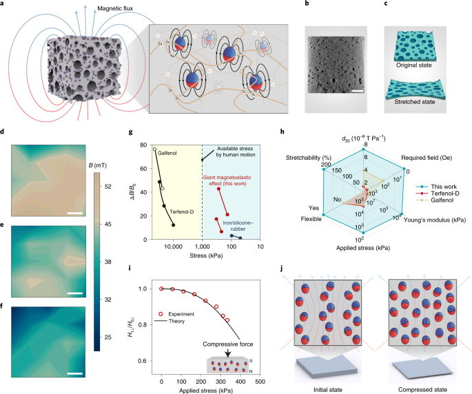
a, Sketch of the porous soft system generating a magnetic flux. Inset: sketch of the internal structure showing micromagnets (red and blue spheres) dispersed in a polymer silicone matrix (orange lines). b, Micro-CT image of the soft system. Scale bar, 0.4 cm. c, Illustration showing the micro-to-nanoscale porosities subjected to a stretch deformation, improving the softness of the system. d–f, Magnetic flux density (B) mappings of the soft system under 0 kPa (d), 139 kPa (e) and 278 kPa (f) compressive stresses. Scale bars, 4 mm. g, Magnetoelastic performance of different systems in terms of applied compressive stress and associated relative magnetic flux density changes (ΔB/B0, where B0 is the initial magnetic flux density without external stress)26,27. Data of giant magnetoelastic effect were taken on both centre and corner of the sample (83 wt%). h, Performance comparison of different magnetoelastic systems in terms of the magnetomechanical coupling factor d33, external magnetic field requirement, Young’s modulus, applied stress, flexibility and stretchability. i, Comparison of the experimental magnetic field reduction (H1⊥/H0⊥, equal to B1⊥/B0⊥) and the wavy chain model prediction showing consistency. B0⊥ was measured to be 46.7 mT. Inset: sketch of the compressive force to quantify the giant magnetoelastic effect. Red and blue spheres represent micromagnets. N and S represent the polarization direction of the soft system under compression. j, Illustration of the magnetic dipole alignment changing the magnetic flux density of the soft system in the initial state and the compressed state based on a wavy chain model. Red and blue spheres represent micromagnets.
To demonstrate the versatility of the soft magnetic system, we fabricated and tested two additional soft systems with SrFe12O19 and Fe3O4 micromagnets, both of which demonstrated the magnetoelastic effect and decreased magnetic flux density under uniaxial stresses (Supplementary Fig. 8 and Supplementary Table 2). However, the magnetomechanical coupling factor d33 (T Pa–1) of the soft systems with the Fe3O4 and SrFe12O19 micromagnets is substantially smaller than that of the soft system with NdFeB. Therefore, the following study will focus on the soft system with NdFeB micromagnets.
To study the fundamental working mechanism behind the giant magnetoelastic effect, we characterized the magnetic field variation in the middle of the system surface under different uniaxial stresses (Fig. 1i). The observed giant magnetoelastic effect resulted from different mechanisms compared to the traditional magnetoelastic effect in Terfenol-D and Galfenol alloys. The latter arises from the realignment of magnet domains and stress-induced magnetic anisotropy under external magnetic fields28, while the giant magnetoelastic effect discovered in our soft systems is attributed to the change of the micromagnet chain structure under mechanical deformation. As illustrated in Fig. 1j, the micromagnets are considered to be single magnetic dipoles and aligned in a wavy chain structure in the initial state after magnetization. In the compressed state, the micromagnet chain structure varies and alternates the dipole–dipole interaction inside the chain and demagnetizing field associated with the decrease of surface magnetic flux density. Once the uniaxial stress is released, the recovery of the micromagnet wavy chain structure reverses the magnetic flux density back to the original. Based on the wavy chain model, the relationship between the vertical magnetic field H⊥ and principal stretch λ could be expressed as (Supplementary Note 2)
where r is the micromagnet radius; a is the aspect ratio of the wavy chain structure; λ is the stretch in the compression direction; M is the magnetization of the micromagnets; k is a constant characterizing the influence of non-ideality, neighbouring chain–chain interaction and macroscopic shape effect on the demagnetizing factor under compressive deformation; b and h are horizontal and vertical distances, respectively, between the neighbouring micromagnets inside the wavy chain (Supplementary Fig. 9); and 0.3006 – f(x) is the dipole alignment factor, which describes the contribution of all other dipoles to the vertical magnetic field of a single dipole in the wavy chain. Under the assumption of an incompressible neo-Hookean solid, the magnetic field H⊥ is further linked to applied nominal stress s in the soft system through
where G is the shear modulus. The aspect ratio a is estimated to be 96. With the measured average r, b and h values of 5.00 µm, 22.01 μm and 24.33 μm (Supplementary Fig. 10), we found that, when k is equal to 0.17, the wavy chain model accurately captures the decrease of vertical magnetic field ratio H1⊥/H0⊥ (equal to B1⊥/B0⊥) with applied uniaxial stress s and fits with the experimental results in Fig. 1i.
Constructing MEGs for biomechanical-to-electrical conversion
The giant magnetoelastic effect is able to convert stress to localized magnetic field variation, which could be further utilized to generate electricity when coupled with magnetic induction. Thus, a soft MEG was developed with a giant magnetomechanical coupling (GMMC) layer and a patterned liquid-metal receiver as the magnetic induction (MI) layer (Fig. 2a). Its working mechanism consists of a two-step conversion process: the giant magnetoelastic effect for biomechanical-to-magnetic conversion and the magnetic induction for magnetic-to-electrical conversion. Since the magnetic field variation can pass through the water without notable intensity decrease, the soft MEG is intrinsically waterproof and could operate stably against heavy perspiration (Fig. 2b). With an all-in-one design, the soft MEG can be bent, twisted and stretched to arbitrary shapes, allowing it to be attached to human skin conformably (Supplementary Fig. 11). According to Faraday’s law, the electrical output of the soft MEG is proportional to both the magnetic field variation in the GMMC layer and the number of liquid-metal turns in the MI layer, which could be optimized to improve biomechanical-to-electrical energy conversion. First, a higher concentration of micromagnets will lead to a larger magnetic field variation and better electrical output (Fig. 2c and Supplementary Fig. 13). However, the softness of the GMMC layer follows a reverse trend with the increase of the micromagnet concentration (Fig. 2d and Supplementary Fig. 14). As a result, 83 wt% is the optimized value that assures both a large magnetic field variation and mechanical softness. Regarding the MI layer, a multilayer structure was adopted to increase the number of liquid-metal turns in a limited surface area (Supplementary Fig. 17). MI layers with different turns and different multilayer structures were fabricated and characterized systematically in Fig. 2e. Both open-circuit voltage (Voc) and Isc show a linear relationship with the number of turns in the MI layer. With the two-layer-structured MI layer, the MEG displays stable Voc and Isc output around 140 mV and 2.7 mA (Fig. 2f). With the three-layer-structured MI layer, the highest Voc and Isc of the soft MEG were measured to be 175 mV and 4.77 mA, respectively, corresponding to a peak power of 450 mW m−2 at the matched load resistance of ~20 Ω (Fig. 2g,h and Supplementary Fig. 18). The working mechanism of our soft MEG distinguishes itself in the community of biomechanical energy conversion with other soft counterparts based on triboelectric and piezoelectric effects29,30,31,32. Via electric dipole alignment, electricity generation based on triboelectric and piezoelectric effects relies on the capacitive conduction, leading to a low current output via electric dipole polarization33. By contrast, the alternating alignment of magnetic dipoles both on and inside the surface of the GMMC layer can be harvested through MI layers remotely using low-resistence liquid-metal turns, boosting the current output of the soft MEG to a much higher level. The measured current density of more than 1 mA cm−2 is higher than that of many biomechanical energy harvesters based on triboelectric29,32 and piezoelectric effects30,31 (Supplementary Table 3). The long-term durability of the soft MEG and its electrical output under versatile mechanical deformations were also characterized and are displayed in Supplementary Figs. 19 and 20−22, respectively.
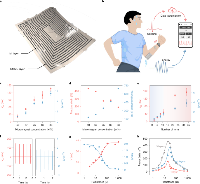
a, The soft MEG is composed of micromagnets inside a polymer matrix as the GMMC layer and a patterned liquid-metal receiver as the MI layer. b, Soft MEGs are sweatproof and can be used for energy and sensing aspects of bioelectronics. PWV, pulse wave velocity; K, K value. c, Optimization of the soft MEG against micromagnet concentration. Error bars are standard deviations of the results from three tests. d, Fracture strain and Young’s modulus of the soft MEG against micromagnet concentration. e, Optimization of the soft MEG against structures of the MI layer; 22 and 33 liquid-metal turns were fabricated using multilayer structures. Error bars are standard deviations of the results from three tests. Shading indicates the transition from single-layered MI structures to multi-layered MI structures. f, Voc and Isc of the soft MEG with a two-layered MI layer. g, The soft MEG with an MI layer of 11 turns demonstrates an ultralow internal impedance of ~20 Ω. V and I are the voltage and current output of the soft MEG, respectively, when connected to a external load. h, Output power dependence on the load resistance for soft MEGs with different MI layers.
Wearable and implantable power generation
The soft MEG can be used to drive wearable bioelectronics, such as a thermometer, a sweat sensor and an electrocardiogram for personalized healthcare (Fig. 3a). A soft MEG with an MI layer of 300 soft copper turns is able to deliver a Isc of 4.27 mA cm−2, Voc of 1.38 V and peak power of 20.17 W m–2 with an internal impedance of ~30 Ω (Fig. 3b and Supplementary Fig. 23). Figure 3c,d presents the Voc and Isc of the soft MEG under continuous hand tapping. The electric output was further boosted and regulated using a toroidal transformer and a Schottky diode bridge (Supplementary Fig. 24). Benefiting from the high output current of the soft MEG, with gentle hand tapping, capacitors of 22, 47 and 100 µF were successfully charged to 3, 2 and 1.1 V within 33 seconds, respectively (Fig. 3e). A soft MEG, with an MI layer of 22 liquid-metal turns, was also able to generate electricity to drive a commercial thermometer for body temperature monitoring (Supplementary Fig. 25).
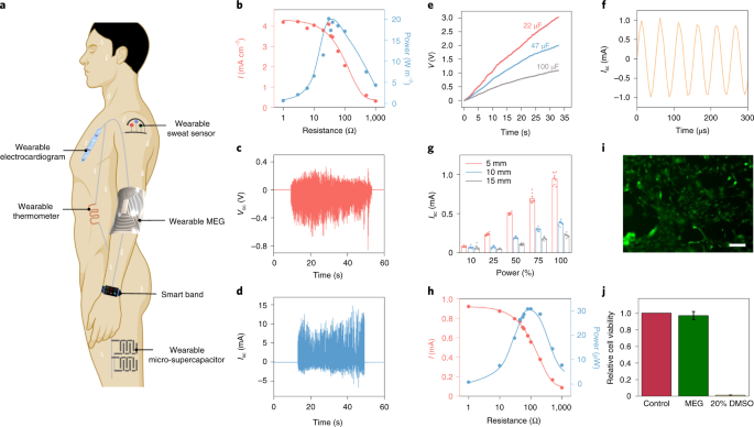
a, Scheme of the soft MEG as a wearable power generation source for small wearable electronics. b, Output current and power of the soft MEG dependence on the load resistances for wearable power generation. c, Voc of the soft MEG under continuous hand tapping. d, Isc of the soft MEG under continuous hand tapping. e, Charging of 22, 47 and 100 µF capacitors by hand tapping the soft MEG. f, Isc waveform of the optimal MEG under 5 mm of porcine tissue with ultrasound excitation power of 100%. g, Isc peak output of the optimal MEG under 5, 10 and 15 mm of porcine tissue with ultrasound excitation of different powers from 10 to 100%. Error bars are standard deviations of the results from eight data points. h, Output current and power of the soft MEG dependence on the load resistances with ultrasound excitation of 100% power at the implantation depth of 5 mm. i, Live/dead assay of human fibroblasts being cultured on the soft MEG for 24 hours. Scale bar, 200 µm. j, Prestoblue assay detects the cell viability (ratio to control) of fibroblasts on the soft MEG. Error bars are standard deviations of the results from three samples. DMSO, dimethylsulfoxide.
Apart from the wearable power generation, a sustainable energy supply for implantable bioelectronic devices remains a highly desired but challenging area. Acoustic waves and ultrasound are safe at low power and can transfer energy for medical implants in vivo through piezoelectric and triboelectric effects regardless of environmental conductivity and transparency34. The soft MEG possesses outstanding electrical output underwater without the need of encapsulation because of the negligible influence of water on the magnetic field. We thus demonstrate the application of the soft MEG as an implantable power source to harvest ultrasound excitation without encapsulation under porcine tissue. A soft MEG with an MI layer of 100 soft copper turns was implanted 5–15 mm underneath the skin (Supplementary Figs. 26 and 27). Control experiments were first performed to identify that the electrical output was mainly from mechanical deformation of the GMMC layer instead of wireless transmission (Supplementary Fig. 28 and Supplementary Note 3). Then an optimal device structure (Supplementary Figs. 29 and 30) was determined at the implantation depth of 5 mm under 20 kHz ultrasound excitation. We characterized the optimal soft MEG ex vivo at different implantation depths with different ultrasound power densities (Fig. 3f,g and Supplementary Figs. 31–33). Performance of the soft MEG increased with increasing ultrasound power and decreasing implantation depth, which can be attributed to the attenuation of the ultrasound inside the layer-structured porcine tissue. The soft MEG exhibited the highest output current of approximately 0.94 mA at 5 mm under ultrasound excitation with 100% power output. This value is approximately five times larger than that of a triboelectric harvester with similar testing conditions34. Peak power of 30.69 µW (Fig. 3h) was reached at 100 Ω, which is comparable to that of many implantable bioelectronics such as pacemakers and neurostimulators, indicating the practicability of the soft MEG34.
Our soft MEGs were confirmed to be biocompatible by using an in vitro culture of human fibroblasts (Fig. 3i,j and Supplementary Fig. 34). The fluorescent image in Fig. 3i shows that the cells exhibit regular morphology, with rare cell death on the soft MEGs. This result is different from that of the negative control group with 20% dimethylsulfoxide, where almost all cells died (Supplementary Fig. 34c). Quantification of cell viability shows that over 95% of human fibroblasts on the soft MEG survived after 24 hours, indicating excellent biocompatibility.
Monitoring of the human cardiovascular system
The sweat-resistant feature is important for continuous monitoring of human physiological signals since sweating is unavoidable and can amount to as much as ten liters per day35. Current working mechanisms require encapsulation layers to be sweatproof, which compromises the sensitivity36. Thus, we also demonstrate feasibility of the soft MEG as a self-powered and sweatproof biosensor to monitor the human arterial pulse. The weak human pulse vibration leads to the deformation of the conformally attached soft MEG and causes a magnetic field distortion through the MI layer, which induces an electromotive force and generates the electric signals (Fig. 4a). As shown in Fig. 4b, the soft MEG could be conveniently worn on the wrist for human pulse monitoring in a wet state. Based on the giant magnetoelastic effect, the output electric current and voltage of the soft MEG remain almost constant even after being submerged in artificial perspiration for seven days (Supplementary Fig. 35). To demonstrate the waterproof feature of the soft MEG as a self-powered pulse sensor towards practical applications, we tested the device both underwater and with human sweat (Fig. 4c). The obtained signals are similar in both situations and contain fine structures such as systolic and diastolic peaks in the waveform benefiting from the high sensitivity. As a result, key parameters including stiffness index, pulse wave velocity, K value, radial augmentation index and left ventricular ejection time can be extracted to evaluate the cardiovascular health status (Fig. 4d and Supplementary Figs. 36–38). Details and calculations of these parameters can be found in Supplementary Note 4. All the cardiovascular parameters withdrawn from the wearable device denote the heart of the human subject in a healthy state and validate the availability of the soft MEG as a self-powered human pulse monitor capable of detecting imperceptible pressure changes.
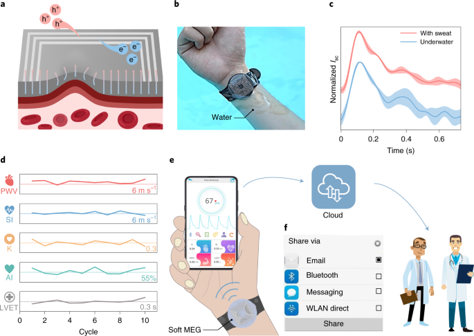
a, Schematic of the self-powered arterial pulse sensing mechanism of the soft MEG. h+, hole; e–, electron. b, Photograph showing a soft MEG worn on the wrist underwater. c, Comparison of the arterial pulse waveforms obtained from the soft MEG underwater and with sweat. The shadow areas indicate the standard deviation of the results from five pulse wave profiles. d, Key arterial parameters extracted from the fine structure of the pulse waveform obtained with artificial perspiration. The dotted lines indicate the values of the different arterial parameters listed at the lower right. PWV, pulse wave velocity; SI, stiffness index; K, K value; AI, radial augmentation index; LVET, left ventricular ejection time. e, Illustration of a soft-MEG-based integrated cardiovascular health monitoring system. f, Specifically designed APP interface for one-click health data sharing. WLAN, wireless local area network.
We further developed a highly integrated cardiovascular health monitoring system (Fig. 4e,f and Supplementary Figs. 39 and 40). All the measured health data can be forwarded with only one click to physicians through email, a cloud service or a message, as displayed in Fig. 4f and Supplementary Fig. 41. Our integrated cardiovascular health monitoring system can continuously and stably provide real-time, patient-generated health data and wirelessly display them in a cellphone application (APP) in a situation with heavy perspiration or with artificial perspiration spraying (Supplementary Video 2).
Outlook
Technically, the electrical output of the soft MEG can be further promoted through a better design of the GMMC layer and more advanced liquid-metal pattern techniques such as three-dimensional printing. Magnetic particle distribution, particle size and polymer matrix microstructure could have a substantial impact on the magnetomechanical coupling of the GMMC layer. Particle aggregates reduce the magnetic flux density and ultimate strain of the layer but do not change the relative variation of the magnetic field under uniaxial stresses (Supplementary Fig. 42 and Supplementary Note 5). As displayed in Supplementary Fig. 43, the GMMC layer with nanomagnets demonstrates a consistently high magnetomechanical coupling factor of up to 6.92 × 10⁻⁸ T Pa–1 under uniaxial stress from 0 to 400 kPa without sacrificing its mechanical softness (Supplementary Note 6). The impact of porosity on the performance of the GMMC layer is displayed in Supplementary Figs. 44 and 45. Generally, high porosity will reduce the Young’s modulus of the GMMC layer and increase the relative magnetic flux density variation without reducing the magnetomechanical coupling factor substantially (Supplementary Note 7). We foresee that by finely programming the size and distribution of magnetic fillers as well as the microstructure of the polymer matrix, a soft magnetic system with an even higher magnetomechanical coupling factor could be obtained in the future.
The giant magnetoelastic effect observed in the soft systems without an external magnetic field is different from the magnetoelastic effect reported in the iron/silicone–rubber systems that need an externally applied magnetic field25,37,38. With a distinct theoretical consideration, the giant magnetoelastic effect observed in the soft systems holds a much higher magnitude . This will lead to a broader application potential in the field of bioelectronics. Thus, when combined with magnetic induction, the invented soft MEG features a high Isc of 4.27 mA cm−2 and Voc of 1.38 V at an internal resistance of ~30 Ω and therefore can find itself in versatile applications in the field of bioelectronics such as powering wearable bioelectronics using body movements, providing implantable power generation under ultrasound excitation without the need of encapsulation and measuring the human pulse wave in the presence of perspiration.
Methods
Fabrication of GMMC layers
GMMC layers were prepared by thoroughly mixing an uncured silicone rubber matrix with non-magnetized neodymium–iron–boron micromagnets and then cured in a heat oven with introduced air bubbles at the micrometre scale. Specifically, Ecoflex 00-30-part A, part B and micromagnets (MQFP-B-20076-088) were blended thoroughly using a stirring rod. The weight ratio of Ecoflex 00-30-part A and part B was kept at 1:1 for all GMMC layers. Micromagnets with weight concentrations of 50%, 67%, 75%, 80% and 83% were used to fabricate different GMMC layers for optimizing the mechanical, magnetic and magnetomechanical properties of the soft system. The porosity-0 sample was prepared by heating the uncured mixture in a vacuum oven. Vacuum degassing was not performed to the porosity-0.187 sample thereafter to introduce air bubbles for a porous structure. The porosity-0.477 sample was prepared by adding an extra 5 wt% of NH4HCO3 (Sigma Aldrich) in the mixture with 80 wt% of micromagnet concentration. The GMMC layer with neodymium–iron–boron nanomagnets was prepared by mixing Ecoflex with 83 wt% of nanomagnets (Nanochemazone, 300–500 nm). All the mixtures were cured at 60 °C in an oven (ThermoFisher) for 3 hours. The non-magnetized soft system was magnetized by applying a magnetic pulse (~2.655 T) using an impulse magnetizer (IM-10-30, ASC Scientific) to import stable remnant magnetization.
Characterization of the micromagnets and GMMC layer
Micromagnet size distribution was determined by SEM images (ZEISS Supra 40VP), and statistical analysis of 300 micromagnets was performed. The morphology and internal structure of the GMMC layer were imaged by SEM (ZEISS Supra 40VP) and in-house Micro-CT (crumpCAT). The mechanical performance of the GMMC layer (width, 5 mm; gauge length, 4.5 mm) was determined using tensile testing by a dynamic mechanical analyser (TA Instruments, RSA III). The nominal stress–strain curves of the GMMC layer were plotted in Supplementary Fig. 14. The Young’s modulus and shear modulus were obtained by fitting the experimental curves with a neo-Hookean model (Supplementary Fig. 15). The magnetized GMMC layer (83 wt%) demonstrated a shear modulus of 230.74 kPa, a Young’s modulus of 692.23 kPa and an ultimate strain of 189.28%.
The magnetic hysteresis loops of the micromagnets and GMMC layers were measured by a SQUID magnetometer (Quantum Design, MPMS 3). The magnetic flux density mappings on the surface of a 2 cm × 2 cm × 0.3 cm GMMC thin membrane under applied uniaxial stresses (0, 139 and 278 kPa) were created by measuring the magnetic flux density of 25 evenly distributed spots using the experimental set-up shown in Supplementary Fig. 7. The magnetic flux density in the middle of the GMMC layer surface was measured under applied stress from 0 to 333.62 kPa consecutively to verify the proposed wavy chain model. The employed Gauss meter (Tunkia, TD8620) for measurement has an axial probe. Therefore, the vertical component of the magnetic field could be measured during the mapping experiments. As a result, the measured magnetic flux density variation under uniaxial stresses could excite the coil in the MI layer for biomechanical-to-electrical energy conversion.
Fabrication of the MI layer
Ga (99.99%) and In (99.99%) ingots were purchased from RotoMetals. Eutectic gallium indium (EGaIn; 74.5 wt% Ga and 25.5 wt% In) was prepared by heating in a muffle furnace (ThermoFisher) at 200 °C for 2 hours. Then, the liquid metal was mixed with 10 wt% Ni particles (99.5%, 5 µm, US Research Nanomaterials) thoroughly using a VWR mini Vortexer to achieve the preferred rheological property for improved processability before any usage (Supplementary Fig. 16). A laser cutting machine (ULTRA R5000, Universal Laser System) was used to cut a polyethylene terephthalate (PET) film as the square helix mask (outer length, 48.18 mm; inner length, 22.86 mm; line-width, 730 µm). Liquid metal was then patterned onto a thin polydimethylsiloxane substrate (PDMS, Sylgard 184, mixing ratio of 40:1) using the PET film mask. Different MI layers (2, 5, 8 and 11 liquid-metal turns) were fabricated using the same patterning technique with the square helix mask of the same dimension and line-width (Supplementary Fig. 17).
For the multilayered MI layer, the mask of the second layer (for example, counterclockwise from outside to inside) was cut in a direction opposite to the masks of the first and third layer (for example, clockwise from outside to inside) to ensure the overall clockwise direction. After patterning each layer, Scotch tape was used to protect the vertical interconnect access and expose it when patterning the next layer. A thin layer of PDMS (mixing ratio of 40:1, ~630 μm) was used to separate and encapsulate each layer without constraining its mechanical stretchability. After the last layer was patterned, another thin PDMS layer (mixing ratio of 20:1, ~630 μm) was used to confine the liquid-metal layer and avoid possible leakage.
Fabrication of soft MEGs
For optimization, a thin PDMS layer (mixing ratio of 40:1) was used as the substrate. Then, MI layers of different turns and different layers were patterned on the substrate. A 2 × 2 cm2 GMMC layer of different micromagnet concentrations was then attached to the surface of the MI layers to form a soft MEG. For the bending, twisting and stretching test, a thin layer of PDMS (mixing ratio of 40:1) was coated on the GMMC layer with 75 wt% micromagnet as the substrate. Then an MI layer (two layers, 11 liquid-metal turns each layer; outer length, 48.18 mm; inner length, 22.86 mm; line-width, 730 µm) was patterned on the PDMS/GMMC substrate. For the self-powered cardiovascular monitoring system, a thin layer of PDMS (mixing ratio of 40:1) was coated on the GMMC layer with 83 wt% micromagnet as the substrate. Then an MI layer (2 layers, 8 liquid-metal turns each layer; outer length, 22.86 mm; inner length, 5.82 mm; line-width, 730 µm) was patterned on the PDMS/GMMC substrate.
Characterization of soft MEGs
A control experiment was first performed to verify the dominance of the giant magnetoelastic effect in biomechanical-to-electrical energy conversion in the soft MEG, which fundamentally distinguishes itself from the traditional electromagnetic generator (Supplementary Fig. 12). Voltage signals of soft MEGs were measured by a Keithley system electrometer (Keithley 6514). Current signals were measured by a Stanford low-noise current preamplifier (model SR570). The stability of the soft MEG (with an MI layer of 22 liquid-metal turns in a two-layer structure) was tested by a calibration electrodynamic transducer (Labworks, ET-126HF) at 20 Hz. For wearable power generation applications, a Schottky diode bridge rectifier (MBSK16SE) was used for a.c./d.c. conversion. A toroidal transformer was used to elevate the output voltage. For implantable power generation applications, an ultrasonic homogenizer (FS-550T) with a 13 mm probe was used. Its output power was calibrated to range from 0 to 330 W. The ultrasound probe was grounded to minimize the noise. In the characterization of implantable MEGs, micromagnets (MQFP-B-20076-089) were used to fabricate the GMMC layer (83 wt%) because it demonstrated a larger output signal in control experiments (Supplementary Fig. 30). An input offset current was used to eliminate unwanted d.c. background current caused by the electron leakage in the SR570 preamplifier. Artificial perspiration was used to test the sweatproof abilities of the soft MEG. To prepare the artificial perspiration, 0.455 g KCl (Sigma Aldrich), 1.55 g NaCl (Sigma Aldrich), 0.0583 g Na2SO4 (Sigma Aldrich), 0.252 g NaHCO3 (Sigma Aldrich), 0.182 g 1 M NH3·H2O (Sigma Aldrich), 0.601 g urea (Alfa Aesar), 0.0092 g uric acid (Alfa Aesar) and 1.26 g 1 M lactic acid solution (Alfa Aesar) were added in 1 l deionized water. A GMMC layer was submerged in the artificial perspiration for 24 h and 168 h and then its electric output was tested.
Biocompatibility test of soft MEGs
Human fibroblasts were purchased from ATCC (ATCC PCS-201-012) and expanded in fibroblast medium consisting of DMEM basal medium (Gibco, 11965), 10% foetal bovine serum (Gibco, 26140079) and 1% penicillin/streptomycin (Gibco, 15140122). These fibroblasts were cultured in an incubator at 37 °C and 5% CO2. For the cell viability assay, before seeding cells onto the soft MEGs, the soft MEGs were plasma treated for 1 minute and coated with 0.1% gelatin for 1 hour. Then fibroblasts were plated and allowed to attach to the soft MEGs for 24 hours. The cell viability was assayed using PrestoBlue Cell Viability Reagent (Invitrogen, A13261) according to the manufacturer’s protocol. Cells were incubated with 10% PrestoBlue reagent for 2 hours. Results were normalized to the control samples (that is, cells seeded in the tissue culture plate). Live and dead assays were performed by using the LIVE/DEAD Cell Imaging Kit (Invitrogen, R37601) according to the manufacturer’s protocol. Cells were incubated with an equal volume of 2× live/dead solution (diluted with the same volume of culture medium) for 30 minutes at room temperature. Epifluorescence images were collected using a Zeiss Axio Observer Z1 inverted fluorescence microscope and analysed using ImageJ.
Circuit and mobile APP design
A hardware signal processing circuit consists of four components: an analogue pulse signal acquisition, an amplifier, a low-pass filter and a micro-controller with a Bluetooth transmission module to a customized mobile phone terminal application. In the cardiovascular monitoring process, the analogue pulse signal was collected from the soft MEG and then amplified by an amplifier (TLC2201) and filtered by a low-pass filter (OP07) to remove both interference signals and environmental noise. The amplification and filtration processes ensure precise expression of the final analogue output signal with sufficient detail for subsequent processing by an analogue-to-digital converter. Thereafter, a micro-controller unit (STM32) was used to collect and convert the analogue pulse signal to a digital pulse signal. Finally, a Bluetooth module (HC-05) was applied to transmit the digital signal to the mobile APP via wireless communication. The circuit was made waterproof to work consistently underwater by coating a thin PDMS layer as the encapsulation. A customized Android application (named Cardiovascular Health Management_MEG) was developed via MIT AI2 Companion for personalized healthcare with a friendly user experience. The APP was designed to continuously acquire pulse signals and in situ analyse health status via heart rate and other key cardiovascular parameters, such as pulse wave velocity, stiffness index, upstroke time and so on.
Human subject study
The soft MEG used for wearable cardiovascular monitoring was tested using human subjects in compliance with all the ethical regulations under a protocol (ID 20-001882) that was approved by the Institutional Review Board at the University of California, Los Angeles. All participating subjects belonged to the University of California, Los Angeles and were provided informed consent before participation in the study.
Data availability
Source data are provided with this paper. Other data generated or analysed during this study are included in the Supplementary Information. Further data are available from the corresponding author upon request.